 |

|
| EPoS Contribution |
|
Fantastic Striations and Where to Find Them: The Origin of Magnetically Aligned Striations in Interstellar Clouds
Che-Yu Chen UVA, Charlottesville, US | |
| Thin, magnetically aligned striations of relatively moderate contrast with the background are commonly observed in both atomic and molecular clouds. They are also prominent in MHD simulations with turbulent converging shocks. The simulated striations develop within a dense, stagnated sheet in the midplane of the post-shock region where magnetically induced converging flows collide. We show analytically that the secondary flows are an inevitable consequence of the jump conditions of oblique MHD shocks. They produce the stagnated, sheet-like sub-layer through a secondary shock when, roughly speaking, the Alfvenic speed in the primary converging flows is supersonic, a condition that is relatively easy to satisfy in interstellar clouds. The dense sub-layer is naturally threaded by a strong magnetic field that lies close to the plane of the sub-layer. The substantial magnetic field makes the sheet highly anisotropic, which is the key to the striation formation. Specifically, perturbations of the primary inflow that vary spatially perpendicular to the magnetic field can easily roll up the sheet around the field lines without bending them, creating corrugations that appear as magnetically aligned striations in column density maps. On the other hand, perturbations that vary spatially along the field lines curve the sub-layer and alter its orientation relative to the magnetic field locally, seeding special locations that become slanted overdense filaments and prestellar cores through enhanced mass accumulation along field lines. In our scenario, the dense sub-layer, which is unique to magnetized oblique shocks, is the birthplace for both magnetically aligned diffuse striations and massive star-forming structures. | |
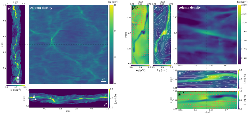 | |
| Caption: Left: Simulated column density map of a 1x1 pc2 core-forming region generated by oblique MHD shocks, which shows clear striations parallel to the magnetic field (whose approximate direction is indicated in each map). Two slices, cut through a striation at x=0.64 pc and y=0.50 pc (dashed lines), illustrate the density structures within the shocked layer approximately parallel (x-axis, bottom) and perpendicular (y-axis, top left) to the post-shock magnetic field. Along either viewing direction, there is a corrugated, thin, dense sub-layer at the midplane of the shock. Right: Zoom-in sample of the simulated striation mentioned above, showing density (top middle and right middle) and magnetic pressure (top left and bottom) slices that are cut through the gray dashed lines indicated in the column density map (top right). White lines in the density maps indicate magnetic field directions, while red arrows in the magnetic pressure maps are gas velocities. | |
| Collaborators: Z.-Y. Li, UVA, US P.K. King, UVA, US L.Fissel, NRAO, US |
Key publication
Suggested Session: Filaments |