LINC-NIRVANA Instrument
LINC-NIRVANA is a complex instrument, comprising a large science channel cryostat, four different wavefront sensors, four deformable mirrors with over 2000 actuators total, eight science-grade detector systems (6 visible, 2 infrared), two calibration units, more than 250 individual lenses and mirrors, 130 motors, 40 separate control systems, and almost 1000 cables. All of this hardware is controlled by a code base of C++, C, and python software totalling more than 450,000 lines.
Learn more about LINC-NIRVANA's opto-mechanics
Learn more about LINC-NIRVANA's adaptive optics
Interactive LINC-NIRVANA Image
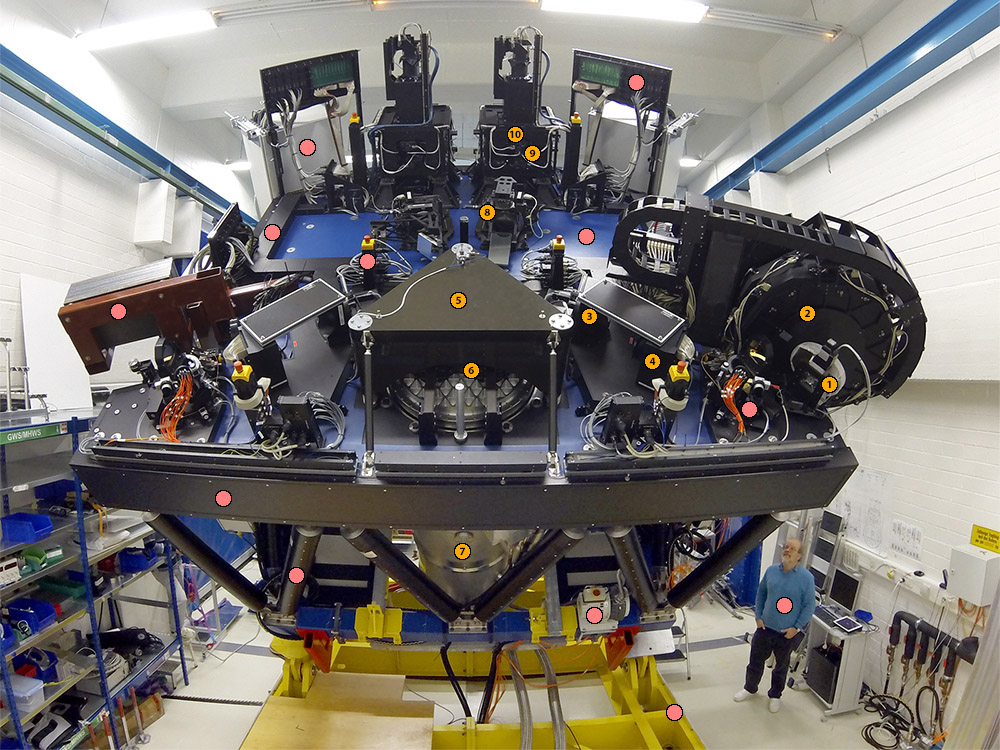
This picture shows LINC-NIRVANA in the MPIA lab just before shipment to the telescope in 2015. Hover your cursor over the coloured dots in the image to learn about individual components of the instrument. To understand the LINC-NIRVANA optical path, follow the orange dots in numerical order.
Annular Mirrors At the two telescope foci, a pair of flat mirrors with a central hole direct the starlight from 2 to 6 arcminute diameter into the Ground Layer Wavefront Sensors and allow the central 2-arcminute field to pass through to the High Layer Wavefront Sensor and the Science Channel.
Optical Bench This large, lightweight composite structure provides stiffness and low thermal expansion for supporting the optical elements of LINC-NIRVANA. This unique approach to observatory optics deployment is covered by US Patent 8,303,313.
Cable Channels LINC-NIRVANA contains almost a thousand cables, each of which contains several to dozens of individual conducting wires. Managing this quantity of signals while keeping the instrument clean and mechanically stable is not a trivial task. The cable channels on the optical bench help maintain order.
Calibration Units These small optical breadboards supply light for internal alignment and calibration of the instrument at visible and near-infrared wavelengths. A motorized mirror places the calibration sources at the input focus.
Coffee Table This carbon fiber composite structure holds the down-folding Piston Mirror that redirects the light from both telescopes into the Science Channel Cryostat. The single piece mirror can shift left to right at high speed to correct for differential atmospheric piston when operating in interferometric mode.
Science Channel Cryostat The light from both telescopes ends up in the large (2 m high) science channel cryostat, which contains a 2048x2048 pixel near-infrared detector, as well as a selection of broad and narrow-band filters.
Warm Dichroics Immediately below the down-folding Piston Mirror, a pair of Warm Dichroics allows the infrared science light to pass through into the Science Channel Cryostat while reflecting the visible light by 90° toward the K-Mirrors and the High-Layer Wavefront Sensors.
Dummy Weight This 700 kg steel structure mimics the weight and dynamic properties of a Ground-Layer Wavefront Sensor. At the time of this photograph, one of the sensors was already at LBT as part of the Pathfinder experiment. Proper weight distribution is a prerequisite to testing the flexure properties of LINC-NIRVANA.
Electronics Cabinets LINC-NIRVANA uses a total of seven large enclosures to house its electronics. These cabinets are sealed and climate controlled to ensure proper performance. They also give off very little heat and thus do not degrade the turbulence environment of the LBT.
Emergency Stop During observations, many of the components on the LINC-NIRVANA bench are in continual motion. To prevent accident and injury, a number of red emergency stop buttons are distributed around the instrument. These will also halt any telescope motions.
Folding Mirrors These flat mirrors direct the incoming light to the Xinetics deformable mirrors (DM) for high-altitude correction. In principle, this location can also host a DM, allowing simultaneous correction of up to 3 layers.
Ground Layer Wavefront Sensors These two large instruments measure the turbulence directly above the telescope and feed the correction information to the LBT's adaptive secondary mirrors.They can each acquire and track on up to twelve separate natural guide stars.
High Layer Wavefront Sensors These two devices measure the atmospheric turbulence at an altitude of 7 km above the telescope and correct it using the Xinetics deformable mirror. Each sensor can sample up to eight natural guide stars.
K-Mirrors These two mechanisms de-rotate the sky, allowing the natural guide stars to fall on the correct locations in the Mid-High Wavefront Sensor. To do this, the K-Mirrors move slowly through an arc during an observation. In this photo one mechanism is vertical, while the other one has rotated 90°.
Bench Support Legs A total of 14 hollow, carbon fiber composite legs, some with wall thickness as thin as 3.5 mm, support the 5.3 tonnes of the LINC-NIRVANA optical bench and its associated components.
Patch Panel Controlling a complex instrument like LINC-NIRVANA requires a lot of cabling to the outside world. This patch panel, which mates with a rectangular hole in the dust cover, carries signals to the Xinetics deformable mirrors, among other components.
Human for Scale The human figure provides a sense of scale for LINC-NIRVANA. During laboratory integration, it was not unusual for 4-5 people to be working at various locations on the optical bench. In many ways, LINC-NIRVANA is the first of the Extremely Large Telescope instruments.
Vacuum Pump This permanently-mounted roughing pump supplements another permanently-mounted turbo-molecular pump to evacuate the LINC-NIRVANA cryostat.
Tipping Rig Mechanical flexure can be a serious problem. To test and characterize LINC-NIRVANA in the lab, this large tipping rig (yellow structure) could rotate the 10.5 tonne instrument through 90°, corresponding to motion from zenith to horizon. Here, LINC-NIRVANA is at about 45°
Trans-Alpino Foci These two bolt circles are the only areas on the LN optical bench that are free of opto-mechanics. In addition to providing human access to the instrument (the bottom of the access ladders rest here), these bolt circles will allow future expansion of LN capabilities.
Patrol Cameras Just behind the K-Mirrors, a beam splitter divides the light between the High-Layer Wavefront Sensors (10) and the Patrol Cameras. The latter provide a full, 2-arcmin field of view to assist in the placement of wavefront sensor star probes and to allow initial acquisition and guiding.
Xinetics Deformable Mirrors These two high-speed deformable mirrors contain 349 actuators each to implement the turbulence correction measured by the Mid-High Wavefront Sensors.